
1. Производ је готовview
The ZK-SMC04 is a versatile DC 10-30V 6.6A Stepper Motor Driver Controller Integrated Board designed for precise control of 42, 57, and 86 series stepper motors. This integrated unit combines driving and control functionalities, offering forward/reverse operation, pulse speed adjustment, and angle control. It supports PLC serial communication for advanced applications.
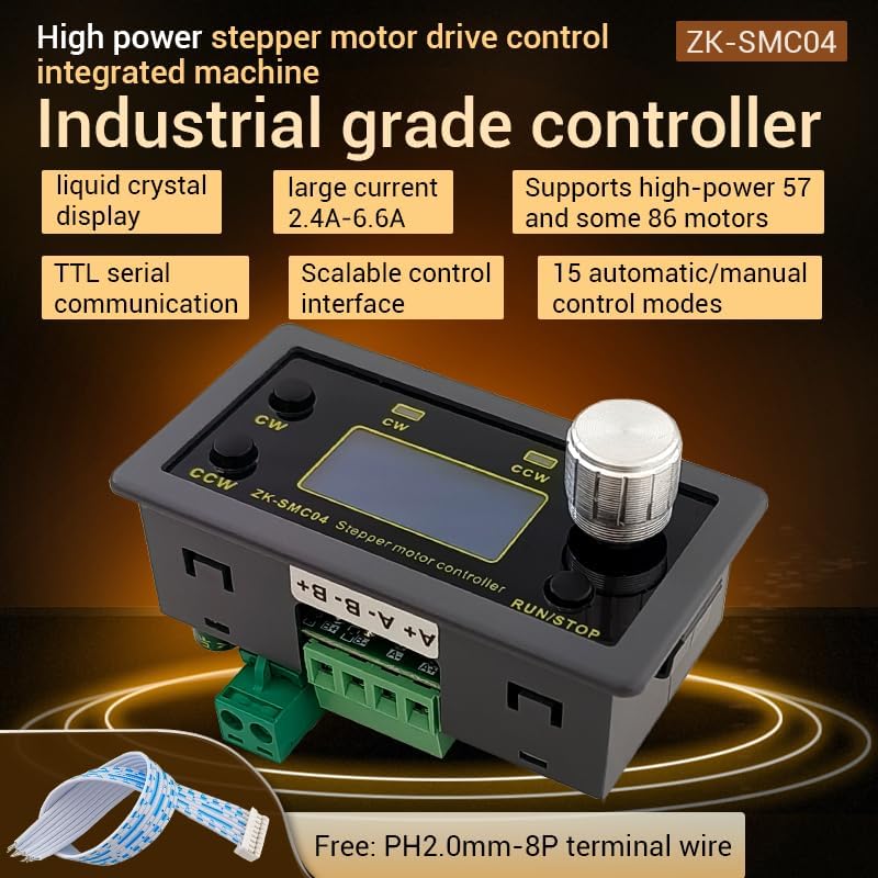
Figure 1.1: ZK-SMC04 Stepper Motor Controller highlighting features such as liquid crystal display, large current capability (2.4A-6.6A), support for high-power 57 and 86 motors, TTL serial communication, scalable control interface, and 15 automatic/manual control modes.
Кључне карактеристике укључују:
- Широк опсег напајања: DC 10-30V universal.
- High Driving Capability: Peak 6.6A.
- High Pulse Frequency: Up to 200KHZ.
- Компатибилност мотора: Adaptable for 42, 57, and 86 stepper motors.
- Режими управљања: 15 automatic/manual control modes.
- Комуникација: TTL serial port for remote communication control.
- Компактан дизајн: Product size 79x43x41mm, recommended hole size 75x39mm for mounting.
2. Спецификације

Figure 2.1: Detailed specifications of the ZK-SMC04 Stepper Motor Driver Controller.
| Параметар | Валуе |
|---|---|
| Модел производа | ЗК-СМЦ04 |
| Назив производа | Drive Control Integrated Machine |
| Суппли Волtage | DC 10-30V (>3A recommended) |
| Излазна струја | 2.4A - 6.6A (Peak) |
| Adaptable Motors | 42, 57, 86 Stepper Motors |
| Пулсе Фрекуенци | Up to 200KHZ |
| Избор режима управљања | 15 options (customizable) |
| Оперативно окружење | -10 ~ 60 °C (non-condensing) |
| Величина шкољке | 79к43к41мм |
| Величина отварања | 75к39мм |
| Тежина артикла | 3.52 унци |
3. Подешавање и инсталација
3.1 Дијаграм ожичења
Proper wiring is essential for the correct operation of the ZK-SMC04. Refer to the diagrams below for power, motor, and control signal connections.

Figure 3.1: Basic product wiring diagram. Connect the DC power supply to the "Power supply +" and "Power supply -" terminals. Connect the stepper motor phases to A+, A-, B+, B- terminals.

Figure 3.2: Expansion interface and serial port output. The 8-pin expansion interface provides connections for external triggers (start/stop, switch direction), limit switches, and output signals. The serial port allows for TTL communication.

Слика 3.3: Прample connection for signal, limit switches, and output. This diagram illustrates how to connect NPN normally open proximity switches for limit detection and push buttons for start/stop and direction change functions.
3.2 Driver Settings (DIP Switches)
The ZK-SMC04 features DIP switches on the board for configuring output current and microstep resolution. Ensure the power is off before adjusting these switches.

Figure 3.4: Driver settings via DIP switches. This image details how to set the output peak current, microstep resolution, chopping mode (Smooth mode SpreadCycle or Silent Mode StealthChop), and holding current (1/2 Run or iRun).
Актуелна поставка:
| Излазна вршна струја | Output Average Current | СВ1 | СВ2 | СВ3 |
|---|---|---|---|---|
| 3.3А | 2.4А | искључено | искључено | искључено |
| 3.7А | 2.7А | on | искључено | искључено |
| 4.1А | 3.1А | искључено | on | искључено |
| 4.5А | 3.4А | on | on | искључено |
| 5.0А | 3.6А | искључено | искључено | on |
| 5.4А | 3.8А | on | искључено | on |
| 5.8А | 4.1А | искључено | on | on |
| 6.6А | 4.7А | on | on | on |
Microstep Resolution Setting:
| СВ4 | СВ5 | Microstep Settings |
|---|---|---|
| искључено | искључено | 8 |
| on | искључено | 16 |
| искључено | on | 32 |
| on | on | 64 |
Chopping Mode (SW6):
- ван: Smooth mode SpreadCycle (Used at high speeds)
- на: Silent Mode StealthChop (Recommended at low speed, operates silently when the motor is at low speed or stopped)
Maintain Current (SW7):
- ван: iRun (running current)
- на: 1/2 iRun (reduces heat generation)
4. Упутство за употребу
The ZK-SMC04 features an intuitive interface with a rotary encoder and buttons for easy operation and parameter adjustment.
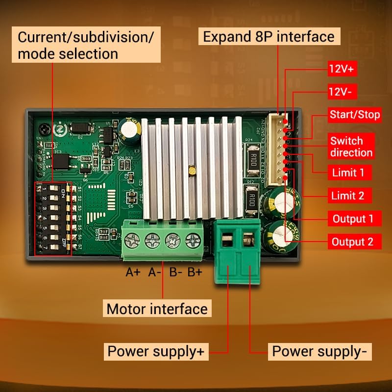
Figure 4.1: Front panel controls. The panel includes buttons for CW (Clockwise) and CCW (Counter-Clockwise) rotation, corresponding indicators, an encoder setting knob for adjustments, and a RUN/STOP button.
4.1 Основни рад
- Старт/Стоп: Притисните тастер РУН / СТОП button to start or stop the motor.
- Контрола правца:
- Притисните CW дугме за ротацију унапред.
- Притисните ЦЦВ button for reverse rotation.
- Speed/Angle Adjustment: Rotate the encoder setting knob to adjust parameters such as speed or angle.
4.2 Menu Navigation and Parameter Settings
The ZK-SMC04 allows for detailed configuration through its menu system. Follow these steps to navigate and adjust parameters:

Figure 4.2: Menu navigation and parameter adjustment. This diagram shows how to stop running and exit, enter menu settings, tune parameters, and exit parameter settings using the rotary encoder and buttons.
- Stop Running and Exit: On the running interface, adjust the speed using the rotary encoder. Press the CW button for forward rotation, CCW button for reverse. Long press the RUN/STOP button to stop running and exit.
- Унесите подешавања менија: From the running interface, long press the encoder to enter the menu settings interface.
- Навигација по менију: In the menu settings interface, rotate the encoder to change the parameter codes from F-01 to F-14. Long press the encoder to save the parameters and exit to enter the running interface.
- Tune Parameters: In the menu settings interface, short press the encoder to enter the F-XX corresponding menu parameter setting state. The parameters will flash. Short press the shift button to rotate the encoder and adjust the parameters. Short press the RUN/STOP button to exit parameter settings and return to the main menu number adjustment interface.
4.3 Menu Functions List
The following table provides a detailed description of each menu function (F-01 to F-14) and their adjustable ranges and default values.

Figure 4.3: Comprehensive list of menu functions and their corresponding actions and settings.
| Број | Функција | Подесиви домет | Подразумевана вредност |
|---|---|---|---|
| Ф-01 | Selection of action flow mode (Table introduction below) | 1 - 15 | 3 |
| Ф-02 | Number of positive rotation pulses/unit (High three bits by rotary encoder, low four bits by display) | 1 - 999999 | 1600 |
| Ф-03 | Forward rotation speed unit: revolutions per minute | 0.1 - 999 | 10 |
| Ф-04 | Number of reverse pulses/unit (High three bits by rotary encoder, low four bits by display) | 1 - 999999 | 1600 |
| Ф-05 | Reverse speed unit: revolutions per minute | 0.1 - 999 | 10 |
| Ф-06 | Number of cycles of work (where 0 = countless times) | 0 - 9999 or countless | 1 |
| Ф-07 | Forward time delay unit: seconds (accuracy ±0.2 seconds) | 0.0 - 999.9 | 0.0 |
| Ф-08 | Reverse time delay unit: seconds (accuracy ±0.2 seconds) | 0.0 - 999.9 | 0.0 |
| Ф-09 | Number of pulses per revolution (1-9999, x10) Unit: 10 (e.g., for 1.8° stepper motor, 8 subdivision = 160, 16 subdivision = 320, 32 subdivision = 640, 64 subdivision = 1280) | 1 - 9999 | 160 |
| Ф-10 | Main interface display content (Up: motor coil speed, Down: revolutions per minute) | 0 - 1 | 00 |
| Ф-11 | The action when pressing the pause button (0: motor slows down and stops slowly, 1: motor immediately stops) | 0 - 1 | 0 |
| Ф-12 | Acceleration and deceleration levels (1-100, 1 being the slowest and 100 being the fastest) | 1 - 100 | 20 |
| Ф-13 | Самозакључујући прекидач | 0 - 1 | 0 |
| Ф-14 | Маил адресу | 1 - 255 | 1 |
5. Одржавање
To ensure the longevity and optimal performance of your ZK-SMC04 Stepper Motor Driver Controller, follow these general maintenance guidelines:
- Одржавати уредним одржавати чистим: Regularly clean the device with a soft, dry cloth to prevent dust accumulation, especially around ventilation openings and connectors.
- Услови животне средине: Operate the controller within the specified temperature and humidity ranges (-10 ~ 60 °C, non-condensing) to prevent damage.
- Сигурне везе: Periodically check all wiring connections to ensure they are secure and free from corrosion. Loose connections can lead to intermittent operation or damage.
- Избегавајте преоптерећење: Ensure the connected motor and power supply are within the specified limits of the ZK-SMC04 to prevent overheating and damage to the driver.
КСНУМКС. Решавање проблема
This section provides solutions to common issues you might encounter with the ZK-SMC04 Stepper Motor Driver Controller.

Figure 6.1: Troubleshooting guide for common operational problems.
| Феномен | Могући проблеми | Мере решења |
|---|---|---|
| The screen doesn't light up | The motor shaft is powerless | Check the power supply circuit to see if it is connected in reverse or supplying power normally. |
| Driver chip protection | Поново укључите. | |
| Мотор се не окреће | The pulse signal is weak | It is recommended to increase the voltage or choose a larger current. |
| The motor does not rotate and keeps vibrating | Check the motor wiring for any issues. | |
| Motor rotation error | Wrong connection of motor wire | Swap two wires of the same phase for any motor (e.g., A+ and A- exchange positions). |
| Неправилан положај | Интерференција сигнала | Remove interference. |
| The motor wire has a broken circuit | Проверите и повежите исправно. | |
| Subdivision error | Set up correct segmentation. | |
| Motor stalling vibration | The current is too small | Повећајте струју. |
| Turn on the mute mode, which is only suitable for low-speed states | Turn off silent mode. | |
| Short acceleration time | Extend acceleration time. | |
| Лов волtage or low current | Appropriately increase the voltagе или струја. |
7. Гаранција и подршка
For warranty information, technical support, or any inquiries regarding the ZK-SMC04 Stepper Motor Driver Controller, please contact GODIYMODULES directly through their official channels or the retailer from whom the product was purchased.
Please refer to the original purchase documentation for specific warranty terms and conditions.